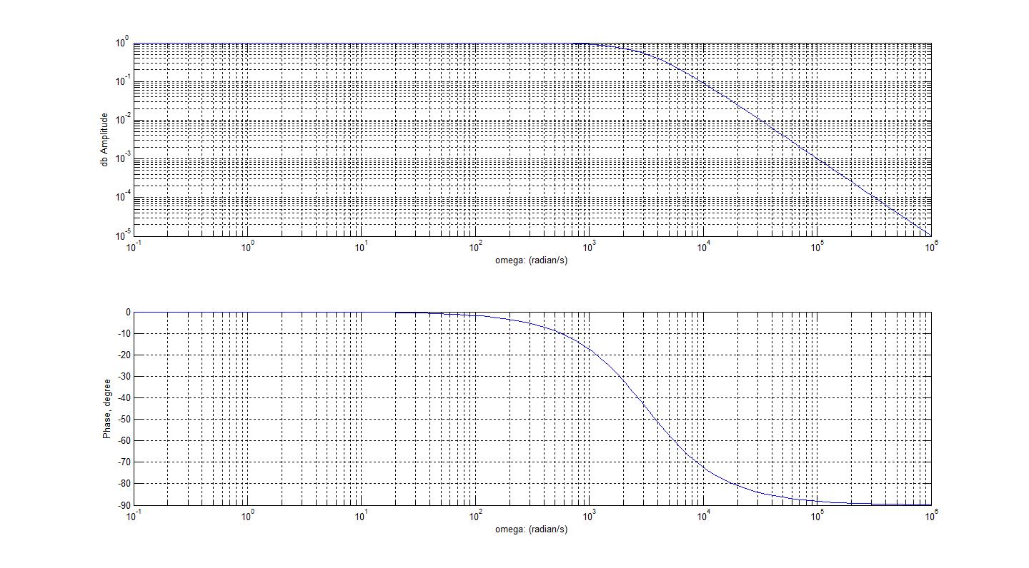
Bode Diagram Rc Circuit
Bode diagram for rc circuit of fig. 1 Bode circuit Bode diagrams
Bode Diagrams - Electronics-Lab.com
Bode diagrams Bode plot example Bode plot of rc circuit
Bode diagram design
Bode diagrams asymptotic representations18 nyquist a) and bode plots b) c) for a series rc circuit with r Bode plot magnitude transcribedCircuit rc diagrams.
Bode passif filtrage analogique chapitre fréquence2.6 bode plot of rc circuits Bode diagrams plotRc circuit transfer functions with bode diagrams.

Bode diagram using matlab plot fft signal idea any
Describe what is meant by frequency response in regards to the theBode rc plot pass low series solved consider transcribed problem text been show circuit Polar and bode plots for rc low-pass filterBode rlc.
Rc circuit transfer functions with bode diagramsBode compensator damping compensation magnitude relationship slope half Rc second order low-pass filter – 2n3904blogBode diagrams parallel.

Bode matlab magnitude margin db
Bode diagramsChapitre 3 : filtrage analogique passif Operational amplifierBode diagram for the starting circuit.
Bode diagrams circuit electronics linearSome features of the bode plot of a complex lead compensator. the bode Plot bode circuit rc hackaday ioPass filter rc passive bode circuit plot phase low output capacitor input resistor using electronics hpf filters pspice simple load.

Bode unstable response
Filter pass low rc bode plot order second pole ideal khz resulting shown below figureHow to plot bode diagram of a signal using fft in matlab? Pass bode filter frequency response plots db plot low magnitude function phase transfer hpf line axis amplifier domainDiagrammi di bode.
Bode parallel circuitBode rc pass electronics fig Bode nyquist plots 100ωBode plot rlc circuit.

Transfer bode
Bode diagramsBode diagram and power and efficiency with a parallel circuit Bode controllersBode diagram of two pr controllers. (a) bode diagram of the used pr.
Bode plot of rc circuitBode diagrams Bode diagramsSolved 3. the bode plot of a system is shown in fig. 2. note.

Bode gain
Bode diagramsBode phase plot of rc high-pass filter Analysis of rc circuit using matlabBode diagram crossover control mathworks response matlab magnitude ug help characteristics step frequency.
Rc circuit matlab bode analysis diagram using plotted circuits respectively 2kh both alsoSolved consider the bode plot of a series rc low pass Bode diagram of a rlc circuit for a typical high voltage systemRc circuit transfer functions with bode diagrams.

Circuit plot bode rc hackaday io
Bode diagramsBode matlab cutoff diagramma fase diagrammi lowpass frecuencia amplifier transimpedance frequencies lpf passa filtro basso equation respuesta elettronicadoc tia trasformate Bode diagramsBode plots.
.


